My new PSU burns out! I fix it, and torture it by cracking water...
My brand new PSU, the most complicated circuit I designed and built just recently, started life in October 2023. It seemed to work pretty well, at least I got through the long and dark winter with it feeding my LED Superlamp. (Most of the time. The rest of that time, I was using it for something it was actually intended for, i.e., the feeding of an experimental new circuit. By the light of a torch.)
Mind the gap - or blow a PCB track!
Then one day towards early Spring, while I was just sitting there, something happened. I remember I was not doing anything in particular when my subconscious alerted me to some weirdness going on. I slowly came to realise that the weirdness was a really sharp bad smell. A smell of something burning, or close to burning. I looked at my bench supply – I clearly remember it was turned on but there was nothing connected to it at the moment. And it seemed to be OK, at least all the LED displays were lit up. But the voltage indicator was strangely zeroed out, clearly in spite of the control settings.
Instinctively, I turned the instrument off, probably even before all the above has fully gone through my head. Sniffing closer confirmed my suspicion that the smell was indeed coming from my bench supply. I was more than a little bit confused – what could cause such a sudden and seemingly unprovoked failure (at idle load!) after several months of trouble-free operation? I mean, design errors would surely have come out by now, and being relatively fresh off the proverbial factory line, we are hopefully still a long way from any possible component wear-out… I was intrigued. It was late in the day and it was already dark (and I just lost the only power supply to my Superlamp), so I called it a day.
And by the first rays of light of the next dawn, this is what I saw:
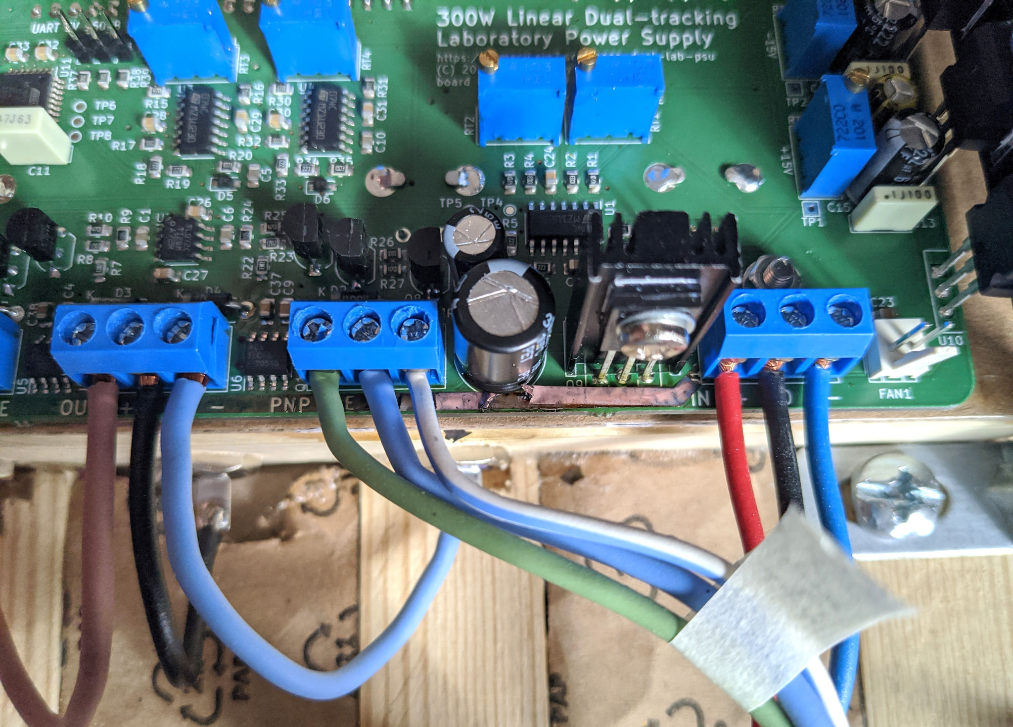
PCB failure (click to enlarge)
Ouch, that PCB track in the middle got badly burned. So badly, in fact, that a couple millimeters of the track simply disappeared (right under the large C7 capacitor, left of the heatsinked Q9). Not for the faint of heart!
Strange that the 2.5A primary side fuse (integrated into the AC inlet) did not melt. And strangely, all the components seemed intact. I would have expected a blown up capacitor or a shattered transistor or IC. But nothing of that sort of catastrophe in sight – everything in seemingly pristine condition. Except for the PCB itself.
Here is a better picture I took after disconnecting the wiring and freeing the board for even closer inspection:
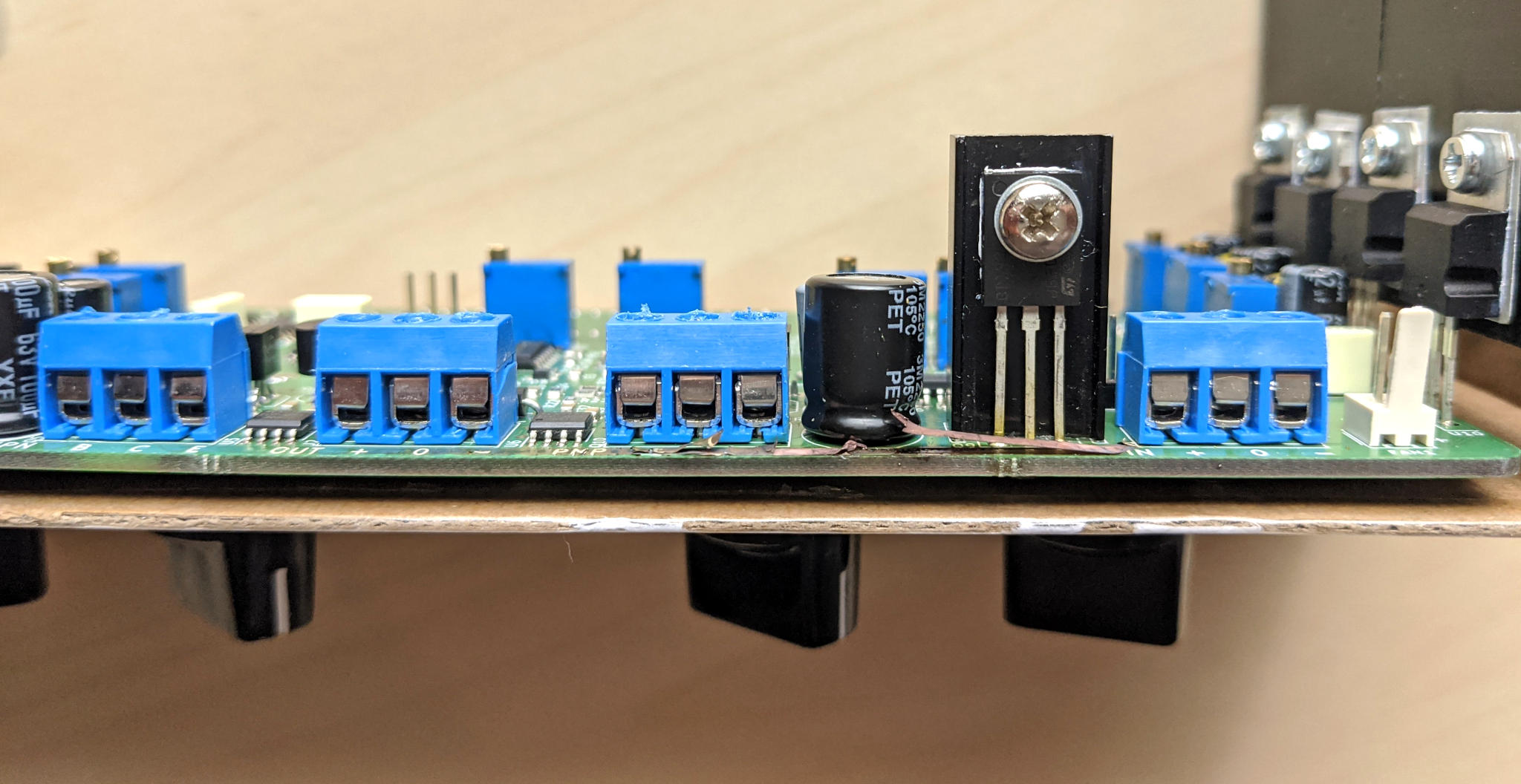
Same failure after disassembly, board plane view (click to enlarge)
So it looks like the VIN+ track (coming right from the unregulated supply) got shorted to the ground plane, right below the ground connection of C7. That track is 80 mils (2 mm) wide, carefully sized to withstand 5A of steady current with only a +20°C rise in temperature. So that alone cannot be the problem – and again, there was zero load when this happened.
Apparently, the 8-mil (0.2 mm) clearance between VIN+ and ground was simply not enough to keep the 40-or-so volts apart. (It was not a turn-on inrush event, as the instrument has been powered on for a while.) Maybe the gap between the copper tracks was dirty (flux remains?) which lead to increased conduction? Maybe the capacitor being there had something to do with it? I did not really know.
Doing some further research I found creepage.com, which contains an online calculator of safety distances for creepage. This term refers to the event of conduction across the surface of an insulator (such as the gap across PCB tracks). The website allows you to get a safe distance between conductors in the face of various voltages and environmental conditions, according to several different industry standards.
So I played around with it and the result I got was (according to the various environmental parameters, coating materials, and safety standards I chose) somewhere between 1.0 mm and 1.2 mm. How embarrassing! My PCB design is thus entirely worthless, because I did not pay any attention to this – and the required distances are much larger than I would have thought. Another hard-earned lesson!
Mending it
Okay, so can we salvage our wreck? After careful inspection and ultimate removal of the charred remains of the track, I reached the conclusion (supported by several measurements) that the rest of the PCB survived intact, including all the components on it. The only actual victim was the positive-side outboard pass transistor, which did not show any external signs of damage, but DMM readouts were contrary to what I would expect of an NPN power transistor that is still kicking alive. So I swapped in a new part there. And I put in a nice and thick insulated copper wire between the screw terminals of VIN+ and the collector of Q5, the only connection that got severed by the burn.
And after some further deliberation (what could possibly go wrong?) I flipped the power on…
And it worked! At least voltages seemed okay (without any load), the readouts reacted to knob action, and no part started to burn. All good?
In a sigh of relief, I said to myself I’m just gonna have to give this baby a good workout!
Cracking water
While originally testing the PSU, I used some wire-wound power inductors in the range of a few to a couple dozen Watts. Now I wanted something bigger and badder: a test load that could steadily sink lots of amperes (at a mostly-resistive impedance) without getting into any trouble!
Enter the old classroom physics experiment I always wanted to try myself: electrolysis. That requires a hefty source of DC current, and this seemed like the perfect occasion.
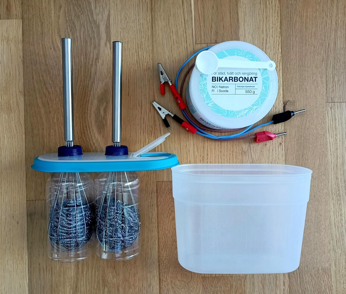
All you need to build an electrolysis device (click to enlarge)
Above you can see all it takes to build an electrolysis tank on a close to zero budget: a lunchbox (of the vertically aligned type), a pair of PET bottles, a pair of stainless steel balloon whisks and steel wool.
The design of my electrolysis tank was greatly inspired by this video. I highly recommend watching it all the way through – I found it to be an excellent source of practical ideas and overall inspiration!
My lunchbox-tank has a well fitting top (with a small, sealable opening useful for pouring stuff in, then closing it for safety). Still, I opted for the milder sodium bicarbonate (baking soda) as the electrolyte instead of the more commonly used sodium hydroxide (caustic soda) or potassium hydroxide, as those are dangerously strong bases. This means less conductivity between the electrodes, but also the absence of hazardous material. Note that the bottle caps are drilled through so the gases are let out at the top. They never mix within the tank.
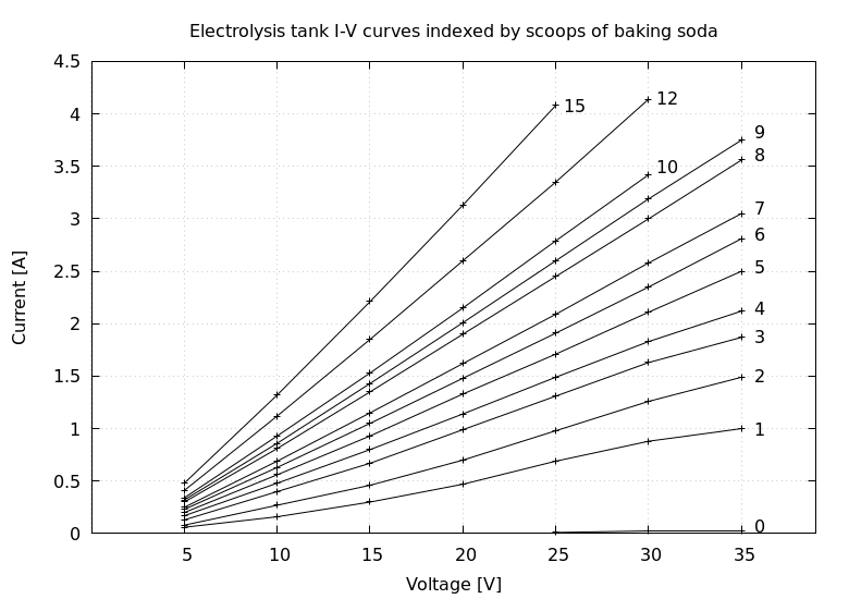
I poured exactly one liter of warm water into the tank and started to record the current at every five volts, from 5V to 35V. After each round, I increased the concentration by adding one scoop (5 ml) of baking soda to the tank. I read voltages and currents directly off the PSU’s digital displays. Here is a plot of the results:
Download the raw data and the gnuplot script if you wish.
In line with prior expectations, conductivity of the electrolytic solution of sodium bicarbonate increases in proportion with the concentration of charged particles (ions) in the water. At a given concentration, the tank behaves pretty much as a resistor (with a linear relationship between its DC voltage and current).
The very first measurement round was made with pure tap water (indexed with the number 0, as there were zero scoops of baking soda in it). There is some current flowing, but very little, equivalent to about 2 kΩ of resistance. That resistance dropped to around 40Ω after the first scoop of soda, 14Ω after 5 scoops, 8Ω after 10 scoops and 6Ω after 15 scoops.
It also seems like there is a tapering effect: the additional conductivity yielded by each new scoop of soda is diminishing. I don’t know enough about the science of this to judge whether this effect is real, but moving upwards, the space between adjacent curves seems to be shrinking. There is some irregularity to it (visible as a gap between graphs 7 and 8, and a smaller one between 4 and 5), but I think that might be due to me not mixing the contents of the tank well enough to dissolve all newly added powder. This might also explain the slight convexity seen in curves 1 and 2: I did not yet realize that I have to mix the tank, so the soda dissolved gradually while I was moving towards higher voltages.
I got a little impatient towards the end, so after the tenth scoop I started adding more at once. First a double (reaching 12 scoops) and then three more (for a total of 15). The bench supply did its part, but it reached the limits of what the mains transformer could supply – above 4 amps, the secondary voltage started to drop below 36V. But the electronics took the beating and nothing melted or burned.
The intensity of bubbling in the tank increased in direct proportion to the current (again, as expected). And the tank also got quite warm, due to the substantial power dissipated in its volume of water.
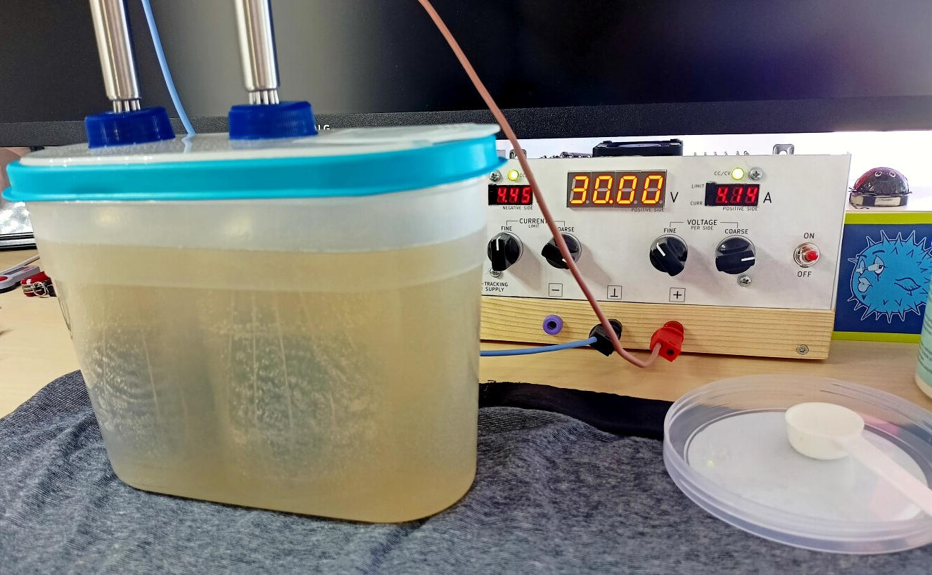
In action, with some 120 Watts absorbed by the tank (click to enlarge)
Conclusion
So the clearances between some of the higher voltage tracks have serious violations of the required distances to be safe from creepage. As a result, one of the tracks has spontaneously self-destructed, but there are a couple more places on the PCB where a similar thing could happen basically any time. I am curious (in a less than ideal way) of whether that would in fact happen…
At the end of the day, this is just another one of several design flaws that would need to be addressed if I ever made a second build of this kind of power supply. But for the time being, I will definitely keep using this device. I have put it through some serious testing and it passed with flying colours. We will see how it holds up, and (if it should come to that) which part of the PCB will give in next!
Having tasted the sweet fruit of 8-mil tracks (and clearances) bringing the ability to design fairly dense circuits, I need to remember the lesson: there must be some real distance to insulate voltages higher than a couple volts. As a reminder, there is this ticking bomb sitting right here on my desk…
What? Did you say I should not be making gaseous hydrogen right next to it? I mean, what could possibly go wrong?
Update: this has sparked some good discussion – thanks for all the comments!