Magnifying LED Superlamp (2500 lumens, dimmable)
The first 15 years or so in the life of this lamp were spent as originally intended: as a TOOLCRAFT magnifying lamp (model 8066/EU), sporting a 22W G10q circular fluorescent bulb. It ran trouble-free for several thousand hours, allowing me to look at small stuff through its large (⌀12 cm) magnifier glass, and serving as a desk and ambient light. It even survived moving across international borders (and then some).
The transparent, bottom half of its plastic case acquired a tint of yellow due to its aging, presumably accelerated by a trickle of UV emanating from within the enclosure. The flexible arm broke at its weakest point, at the tilting end where it meets the lamp head. The broken piece was replaced by a bit of scrap fiberboard many years ago.
On a dark, sad day last autumn, the lamp got terminally ill and unfit for its job. It began emitting some high-pitched, whining noise, and its light started vibrating in a most unpleasant fashion. A replacement light bulb (which I got at a small discount, as stock being phased out of the market) did not solve this, and in the span of a mere couple days, the new bulb developed even worse vibrations than its long-time predecessor, and finally went belly up. Immediately and in a state of mild panic, I started to look for a replacement of the complete lamp. I need this thing (or its close equivalent) on my desk at all times!
However, I was not pleased with what I found. I was not surprised that fluorescent bulbs (and lamps based on them) have become all but extinct, and all kinds of lamp on offer are LED based. But the model that came closest to my lamp offered a measly 550 lumens or so, and there were complaints about the quality of the looking glass among its customer reviews. It was, however, still pretty expensive. And everything else looked comically inadequate compared to my lamp, which I estimate to have had about 1200 lumens.
So I hesitated about making a purchase, and thought about my dead old lamp. It still had at least half of a good lamp in it: the flexible arms with steel springs, the large (and pleasantly distortion-free) magnifying glass, the on/off switch, and some cable. Should I throw away all that value, and then fork out a hefty sum of money for a brand new (yet still inferior) model? No way! All I need to add is some actual light emitting device, and I have a pretty good lamp!
LEDs, bright white LEDs…
And thus the challenge was born. What technology to use? The electronic ballast (bulb driver circuit) inside the lamp did not seem faulty, but I only did a superficial inspection in the vain hope of finding some obvious failure I could easily fix as a cop-out (and carry on with the lamp as is). At any rate, that circuit was worn-out, and even if it were not so, with dangerous voltages inside (direct-rectified mains, etc.), I did not feel comfortable tinkering with it.
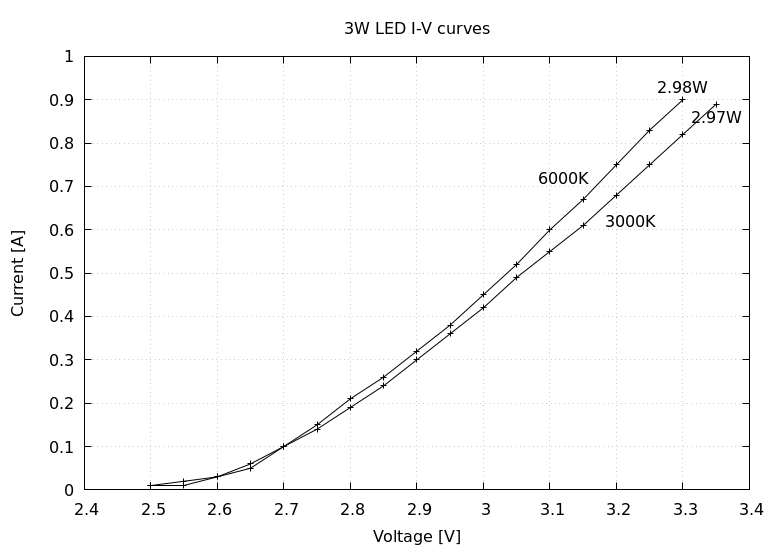
So, in the year 2023, it became obvious that a newly made light source is going to be based on LEDs. High-power, bright white LEDs for lighting purposes. Based on easy availability (friendly local electronics store) I considered two variants of what is essentially the same stock: JSLS-3W-UW (3W 6000K, white) and JSLS-3W-WW (3W 3000K, warm white). After testing a single specimen of both, I went with the whiter variant (datasheet). I also did some measurements to determine optimal (safe) currents for both types of LED (attached to a heatsink), summarized in the below graph:
Download the raw data and the gnuplot script if you wish.
Measurements were carried out up to the point where power (calculated as the product of DC voltage and current) reaches the nominal value of 3W. The LEDs behave quite similarly (as expected); I can’t tell whether the slight difference between the two types is random or systemic. The resistance exhibits a strong thermal effect: as the device heats up, its forward voltage (at constant current) will drop. If, on the other hand, the voltage is held constant, it will lead to higher current with increasing temperature. The small curve irregularities are most likely due to this effect (the LEDs getting relatively warmer or cooler as I managed to go through the experiment at an uncontrolled rate).
Conditions could be better controlled, but I only wanted a quick check to see which of the allowed maxima (forward current or dissipation) in the datasheet would act as the practical upper limit. It turns out the rated current of 700 mA corresponds to about 2.2W at around 3.2 V forward voltage; one would need close to 900 mA to reach 3W of dissipated power (but well past the current limit, so not a safe operating point).
While we’re at it, I would prefer a lamp with controllable intensity (so I can rightfully call it an upgrade as opposed to a mere repair) – not such a big ask considering that LEDs are eminently dimmable. Of course, it should be really bright when set to max, but it should be continuously dimmable from there, with absolutely no flicker, ideally down to zero!
So in theory, it’s a simple matter of putting a bunch of high-intensity white LEDs on an appropriate surface (arranged around the magnifying glass, facing down) and supplying them with a constant, controlled DC current. In theory, we are golden.
Practical (mechanical) matters
Unfortunately, we need to solve this in practice. And that brings in all the pedestrian details of mechanical construction: What sheet material to use (that we can cut to shape, and that will also act as a heatsink)? How to fasten things so they do not fall apart and also do not crack from the tension (considering that I wanted to keep intact as much as possible of the well-fitting but fragile plastic case around the magnifying glass)? Oh, and any driver circuit I construct must fit into the already existing space within the lamp – in fact, it better be at most as large (in all directions) as its predecessor, if I am hoping to assemble it again! The electrical side of all this (providing a source of DC power and driving the LEDs) seemed rather trivial in comparison, or at least I felt that I had the right tools to tackle that job.
So I began flexing my dumpster-diving muscle and in short order, I came up with a couple items that looked, well, interesting. One of them was an old stove tray (baking form) with a rather large and flat bottom, pressed of some kind of steel. (I knew it was not aluminium because it was enthusiastically magnetic.) I laid the upper half of my gutted lamp-head down the middle of it, and marked it around with a felt-tip pen (both on the outside and the hole on the inside, for the magnifying glass).
I thus had my homework right there in front of me. Completely unversed in the industry of preparing and manufacturing objects of metal, I tried and discarded tools that proved wholly inadequate. Then I discovered a set of cutting discs specially for cutting metal, adequate for my dremel tool. I bought a bunch of them and finally got to work. Cutting an elongated hole in sheet metal (even if only 0.7 mm thick) became a very loud and very messy proposition. But I carried on, wearing both ear and eye protection, and arranged things so the metal dust would fly away from me (onto a tiled wall that is easily cleaned afterwards). It took me hours of work, lots of concentration, and about half of a cutting disc to go through all the cutting there was to do. Drilling holes into the same sheet was, in comparison, a walk in the park. A mere couple hours later I had a sheet of steel, precisely cut and drilled, fitting the upper half of the plastic lamp case from below, closing the cavity where the lower part (enclosing the circular bulb and the ballast panel) used to be.
Electronics
How many LEDs to use, and how to supply them with up to 700 mA of (average) current in a controlled manner?
To answer both questions, I needed a concrete piece of DC supply to build my LED driver on. That surfaced as another fruit of my dumpster-diving: a 65W Lenovo laptop charger (AC adapter). These things are ubiquitous (in electronics trash, that is): people throw them away, not knowing what to do with them when their laptop dies, even though they are practically certain to work fine. Well, perhaps not for their originally intended purpose, but they are sturdy, well optimized switch-mode power supplies with negligible quiescent consumption, made for tough loads. The one I got was rated 20V 3.25A on the output side. The open-circuit output voltage was a bit higher, but not by much: 20.5V.
Taking this rating and the circular geometry of the lamp’s head into account, I decided to use 12 LEDs evenly distributed along a circle, just like the numbers on a clock’s face. Electrically, the LEDs are divided into two parallel branches of six LEDs in series each. That makes for a maximum LED voltage of 3.3V (just a little over the 3.2V needed to achieve the desired current) and a total driving current of 1.4A (way below the full capability of this laptop brick). With a small-value resisor ballast of about 1Ω inserted in both branches, the voltage will be just fine.
To control brightness, I went with pulse-width modulation, a simple form of switch-mode power conversion (in our case, a buck converter) to achieve very high power efficiency (at least compared to e.g., using a linear regulator to control the DC voltage across the LEDs). This is possible because it makes no difference to the human eye (above a certain frequency) and the LEDs are well suited to being driven with impulses. For my circuit, I took inspiration from the “Superlamp” published in Horowitz & Hill’s seminal work The Art of Electronics (3rd ed.) as Figure 12.63 on pp.834. This is a simple oscillator built with a CMOS variant of the vintage 555 timer chip, arranged for fixed frequency but adjustable duty cycle. Here is my variation on this theme:

Drive circuit schematic (click for PDF)
I made some minor adjustments to the original circuit, in part to swap in components readily available from my drawers, and also because my supply voltage was higher than what the 555 can operate from (hence the 7812). But mostly because the IRF3205 power MOSFET I had at hand was such a heavy-duty device (several thousand picofarads gate capacitance!) that the 555 had trouble driving it directly at the desired switching frequency. So I inserted an intermediate MOSFET-driving stage with a 2N7000. This way I got switching to work at a measured rate of 24kHz for the full range of duty cycles. However, this intermediate stage acts as a logic inverter, so the two ends of the potentiometer got swapped to maintain the “normal” direction of control: maximum light intensity occurs at the CW (clockwise) end, zero light at the CCW (counter-clockwise) end. This is just a small detail to keep in mind, otherwise the circuit works exactly as you would expect.
The reason for R1 and R2 being two separate resistors was to stay within their power rating of 125mW; their total value was experimentally set to achieve a sufficiently low RDS(ON), as determined through a proxy measurement of the DC voltage drop on Q1 when turned on 100% of the time. R3 and R4 are the ballast resistors mentioned above. Due to the very limited volume available within the lamp body, I took the liberty of omitting the large capacitor and rectifier diode from the AoE design, speculating that a sturdy laptop supply would surely handle a nastier load (at less than half of its rated power capacity) just fine.
After the usual experimental (breadboarding) stage, I built the circuit on a piece of one-sided perf board cut to the same size as the original lightbulb ballast circuit. Below you can see all the parts (old and new) making up the lamp, including the electronics panels in the middle: my new LED driver above the old electronics. (I have already disposed of the lightbulbs and the transparent, lower part of the housing.)
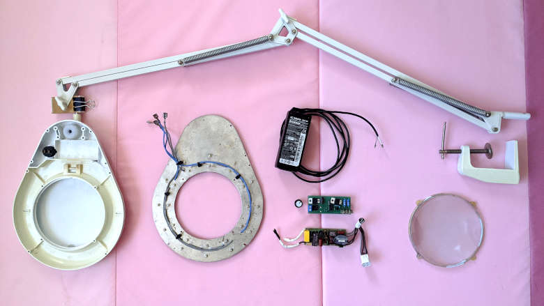
Parts, old and new (click to enlarge)
As you can see, all LEDs are bolted on and fastened with two nuts, and there are two additional holes for threading through each LED’s wiring from front to back.
Below is a closer image I took in the course of assembling the lamp, to make sure everything works before the screws are tightened. Note how the new panel fits into the place of the old; a ⌀6 mm hole was drilled to accommodate the axis of the brightness adjustment trimmer protruding through the plastic housing. Also note the yellow discoloration of the otherwise white plastic, a remnant of radiation from the fluorescent bulb that used to be there.
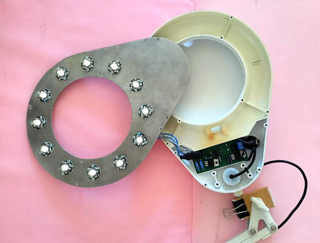
Final test before assembly (click to enlarge)
In this state it was easy to verify operation from zero to full brightness. Welding glasses would have been nice, as my desire for a really bright lamp was fulfilled! I was satisfied to find that the IRF3205 did the job of switching without any effort – I was barely able to feel with my finger that it got a little warmer than its surroundings. Or maybe I just imagined it, I don’t know. On the other hand, the two series resistors R3 and R4 got pretty hot (as expected, dissipating close to 600mW apiece). They also gave me a convenient means to check the LED currents via their measured voltage drops. It all worked out fine, with the maximum current just below 700 mA on both branches. Perfect!
And here is the finished, fully assembled lamp:
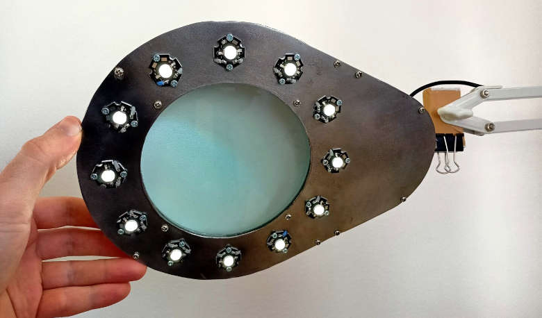
Lamp head from underneath (click to enlarge)
Note the extra knob on top for controlling the brightness:
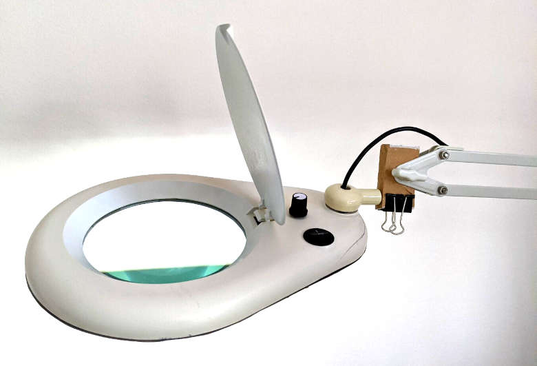
Lamp head with newly added brightness knob (click to enlarge)
Yeah, there are cracks along the edges of the old plastic housing (carefully glued to stop the breakage). Those are not new. This lamp is old, and now I paved its way to get even older!
Conclusion
And so I fixed it! Or, actually, I improved on the original design by a wide margin: Better, cleaner light, brighter than ever, and fully dimmable! The light is fully static to the eye (even at the low end of brightness) and can be finely controlled. Also, better serviceability – if anything breaks, I can easily fix it, both because I know the circuit and because there are no high voltages inside. That said, I expect a practically infinite lifetime from this circuit, at least from the electronics. (I might need to fix and mend the mechanical parts in case they break. I am prepared to sculpt a whole new lamp head, if needed, if I can’t find another one from a junk store.) As a bonus, I also got to recycle a laptop AC supply and a piece of junk metal.
Given the rated luminous intensity of the LEDs (220 lumens at a forward current of 700 mA) I conservatively estimate the lamp to emit about 2500 lumens when turned up to the max. That is a lot of light, but not too much – I tend to use it from time to time, even if (working closely under the glass) I usually choose a lower setting. That also helps with keeping the lamp head from heating up too much. At its max, the lamp consumes around 28W of power from the Lenovo brick, and most of that goes into heating the metal plate, so… it can get pretty hot! But as said, I tend to avoid that and drive the lamp at more modest intensities, still easily in the thousand-lumen range, where it runs much cooler.
