The EMMA SuperTorch
There is never enough light, is there? Especially during the Nordic vinterhalvår (a lovely Swedish word for the half year that is winter).
And besides, I needed some excuse to do a no-stress chill-out hardware project for testing out some PCB manufacturing details, such as curved corners and hole cut-outs. I also wanted to try my hands at building a USB-chargeable portable circuit powered by a 18650-size LiPo battery – that know-how is going to be useful in any number of future gadgets. And above all, this is going to be lots of fun, with all the light emitting functionality completely defined in software. This way the actual workings can be tuned or completely altered long after the electronics is done!
The naming reflects the fact that this torch is dedicated to its final recipient and proud owner Emma, who agrees with me that it is super cool, super bright and super fun to use!
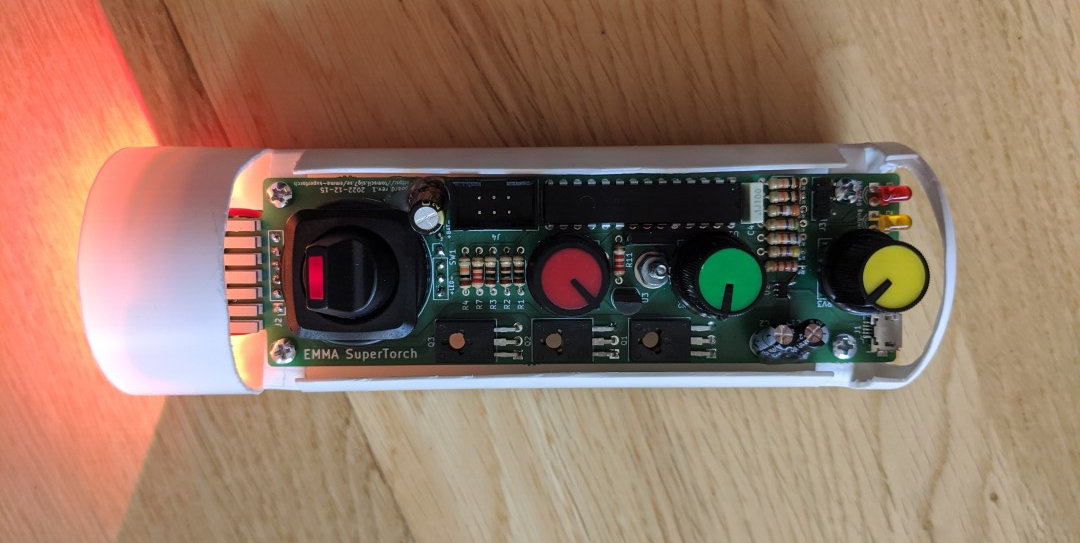
The EMMA SuperTorch (click to enlarge)
Features
- High-power (3W) RGB LED light: red 40-60 lm; green 70-90 lm; blue 15-30 lm according to datasheet
- Large on/off switch with embedded red LED indicating battery level via slow pulse-width modulated blinking
- Three adjustment knobs: Mode (red), Luminance (green) and Frequency (yellow) to manipulate several available software-defined lighting modes
- Powered by a single built-in 18650 LiPo cell (rated 3.7V 2200mAh)
- Rechargeable via micro-USB (i.e., any pre-USB-C phone charger)
- Indicator LEDs for low battery (red) and charging (amber)
- Built with the ubiquitous ATmega328P MCU; in-circuit programmable
The complete schematic
The schematic is shown below; click for the fully sized sheet or download it in PDF:
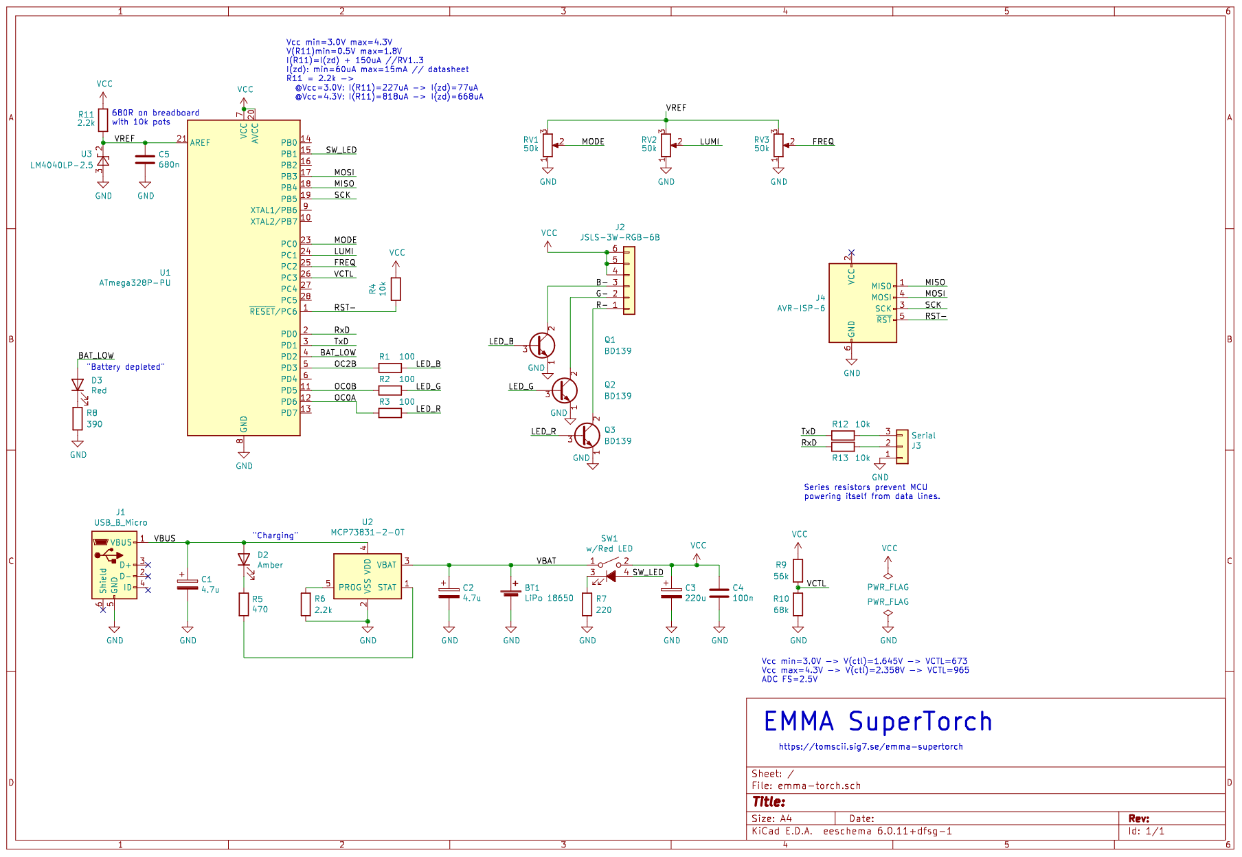
Schematic (click for full resolution), PDF
Not much explanation needed here, just a few points of interest:
- The battery charging functionality is handled by a chip ready-made for this purpose, the Microchip MCP73831-2.
- The control pots are just voltage dividers and their taps go directly to ADC channels on the MCU. All functions are defined in software!
- Speaking of the ADC, there is an LM4040 of the 2.5V variant to ensure a stable and precise reference voltage, something that a battery-powered device really needs.
- The power LED channels are driven by plain old NPN transistors directly controlled by MCU output pins.
Breadboard-driven development
The first obstacle I ran into: the 3W RGB LED I was eyeing for this application suddenly went out of stock, and I spent about two months waiting for it to become available again. In the meantime, I created a version based on an ordinary common-cathode 5mm RGB LED, which allowed me to build the digital part of the circuit and knock myself out with the software.
Once the coveted part arrived, I fastened it on a small BGA heatsink and added the transistor driver stage, with MCU-driven BD139 transistors switching each LED channel. Here’s how it looked:
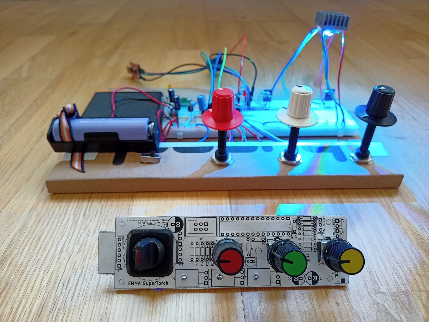
Early breadboard version, with PCB model in front (click to enlarge)
As much as I trust the KiCAD component library and my vernier caliper, printing out the PCB layout on paper, gluing it on a piece of scrap cardboard and cutting it out is something I still like to do as cheap insurance that the components I have on the table actually fit their footprints. The sharp, rigid legs of through-hole pots could be stuck into the cardboard with ease, so I got a very good sense of how the finished device would look.
PCB design
The focal point of this project, as mentioned in the introduction, has been the PCB design. This is my first PCB with a non-rectangular shape; below is the board outline with pads and silkscreen on both sides:
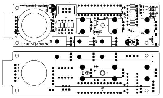
PCB outline
A vanilla two-layer board of low complexity. Dimensions: 34.5mm x 123.5mm. Manufactured by AISLER.
The protrusion on the left is meant to be sandwiched between two adjacent ribs of the LED heatsink. And there are rounded corners to make it slide smoothly into one’s hand (oh, let’s forget about all those spiky solder joints on the underside for a moment).
Now that I have gotten some real PCB design experience, I can say that in retrospect, I thought routing (coming up with the actual copper track placements) would be the hardest part. But actually, that is not the case at all. The hardest part is placement – i.e., finding the best place of each component – which is the natural prerequisite to routing. I find that I routinely spend much more time fidgeting around with the components (with rats nest on) than I initially thought I would. But once I’m satisfied, actually drawing the copper routes becomes sort of trivial, and gets completed real quick (compared to the preceding phase). Of course, there are small adjustments to be made, nudging a component here and there, but those should be minor and not uproot the whole routing in progress.
In the case of this project, I found it a bit challenging to fit everything into the relatively elongated, thin shape of the torch, but I am pleased with the final result. The only tricky thing was to ensure that the battery holder on the bottom side coexists in peace with the pots on the front side of the board. This also presents some ordering constraints when mounting the components: several solder pads (in effect, the majority of the board’s solder side) becomes inaccessible after the battery holder is fastened in place. So that is left as one of the finishing touches.
The same board design, but a bit nicer looking in the KiCAD 3D model view:
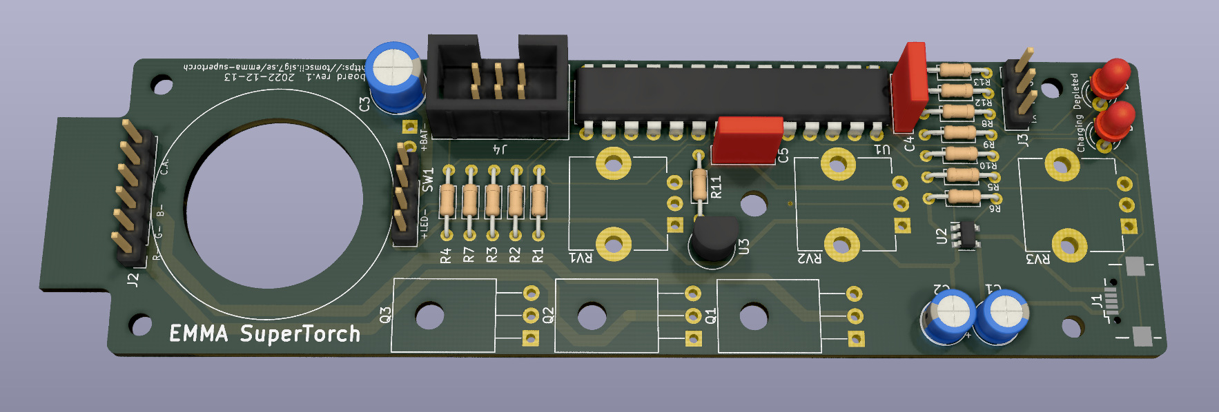
3D board view in KiCAD (click to enlarge)
I think that’s pretty nice, save for the lack of 3D models for some components such as the micro-USB socket and the pots, as well as the switch to be fastened into the giant hole. Oh well, I guess there is no substitute for reality:
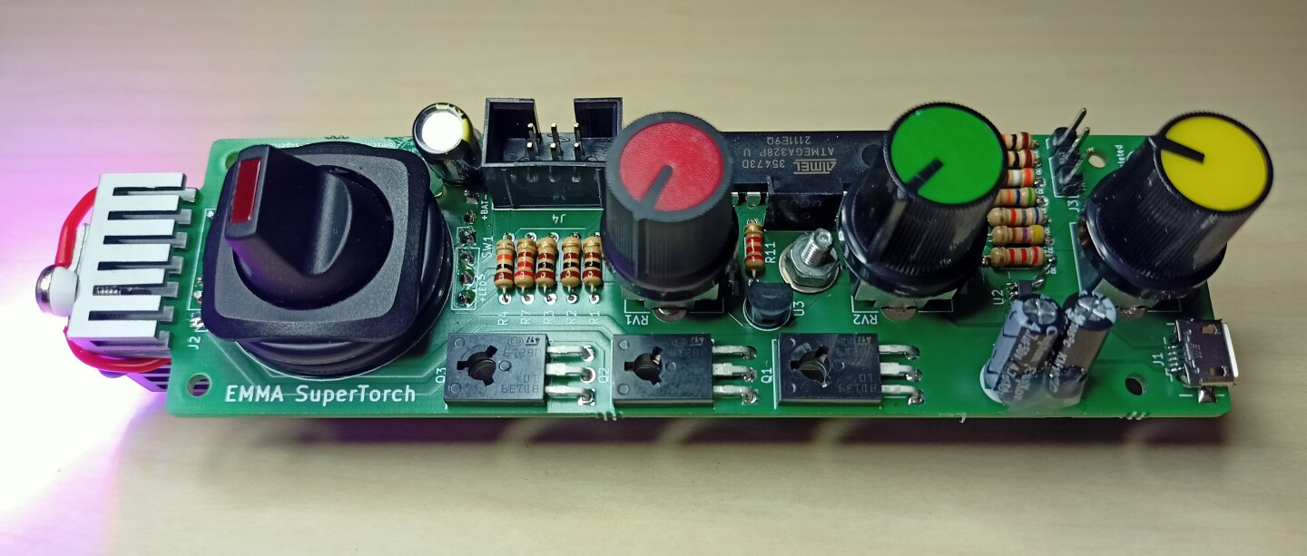
Actually realised electronics (click to enlarge)
Ain’t it cute? Oh yes, those are rubber O-rings under the on/off switch, to make it flush with the pots. For some reason prototyping newly designed stuff tends to lead to these weird surprises. Maybe I should stick to writing software, which can be shamelessly fixed before anyone notices. Or maybe I should also learn some mechanical CAD software, I don’t know.
Software
On the input side of the realtime control
loop
the ADC continuously runs, round-robin sampling the channels. On
completion of each conversion, the ADC
ISR
stores the raw value for subsequent
averaging
and triggers a new conversion on the next channel, going around the
four channels used: three control pots and one VCTL, the
divided-down supply voltage. The latter is used to protect against
bringing the battery into deep depletion: the software is able to shut
down the power, turn on the “battery depleted” red LED and halt the
MCU on
crossing
the low battery
threshold
set at 3.2V.
Speaking of battery depletion: the built-in red light of the on/off switch is driven by a 1 Hz square wave, with a duty cycle reflecting the “battery charge percentage”. In other words, after charging the battery there will be very short blackouts in an almost continuous red light. These blackouts will become longer as the battery discharges, and at the other extreme there will be very short pulses of red light just before reaching the “battery depleted” threshold. This provides ample time to notice that it is time to charge the battery: a nice, entirely software-driven usability enhancement.
On the output side, three channels of pulse-width modulation are controlled by the PWM module. No surprises here: pwm_set_leds provides the obvious interface to controlling the power LED. The PWM frequency is about 3.9 kHz, the 1 MHz MCU clock divided by 256.
In between the input and the output, the DDS
module
is used to generate ramp-up and ramp-down signals of various relative
phase. Having a waveform stored in memory (or computed on the fly, as
is the case in
dds_get_ramp)
and then reading out values at offsets controlled by a phase increment
is the essence of direct digital
synthesis, a
powerful technique for generating signals in a digital system. I
initially planned to use sinewaves (still there in the code, just
excluded via #if 0 ... #endif) but eventually, phase-offset ramps
produced the best in terms of visual effects.
Control programs are implemented as cases within dds_tick, one case per each of N modes, where each mode stretches 1/N-th part of the full range of input values. I think of this as a nice way of employing an analog pot as a rotary switch (with the number of positions flexible in software), if one is not too keen on mechanical feedback while operating it.
Here are the current modes, from the minimum position of Mode towards the maximum:
-
Static color: the Frequency knob controls the color (along a color circle not entirely unlike the color picker wheel in The Gimp, etc). The Luminance knob controls the strength of the light.
There is a special case for Frequency turned all the way down: in this case the light will be white. So one has a conventional white-light torch with brightness controlled via Luminance.
-
Continuously changing colors: the color will rotate along the imaginary color wheel, with a speed controlled by Frequency and brightness set by the Luminance knob.
-
Discrete colors: same as the previous mode, but the color output is quantized to the nearest of 8 equally spaced colors.
-
Stroboscope: the torch will output very short flashes of white light. Frequency controls how frequent the flashes are; Luminance controls their brightness.
Housing
As smooth as those PCB corners are, it is highly desirable to have some housing to give the torch a more conventional cylindrical form. As luck would have it, an empty plastic shampoo bottle was just about to be disposed into the bin. I tried my hands on it with a sharp knife, and discovered that it was easy to cut. After some ad-hoc handywork, here is the result:
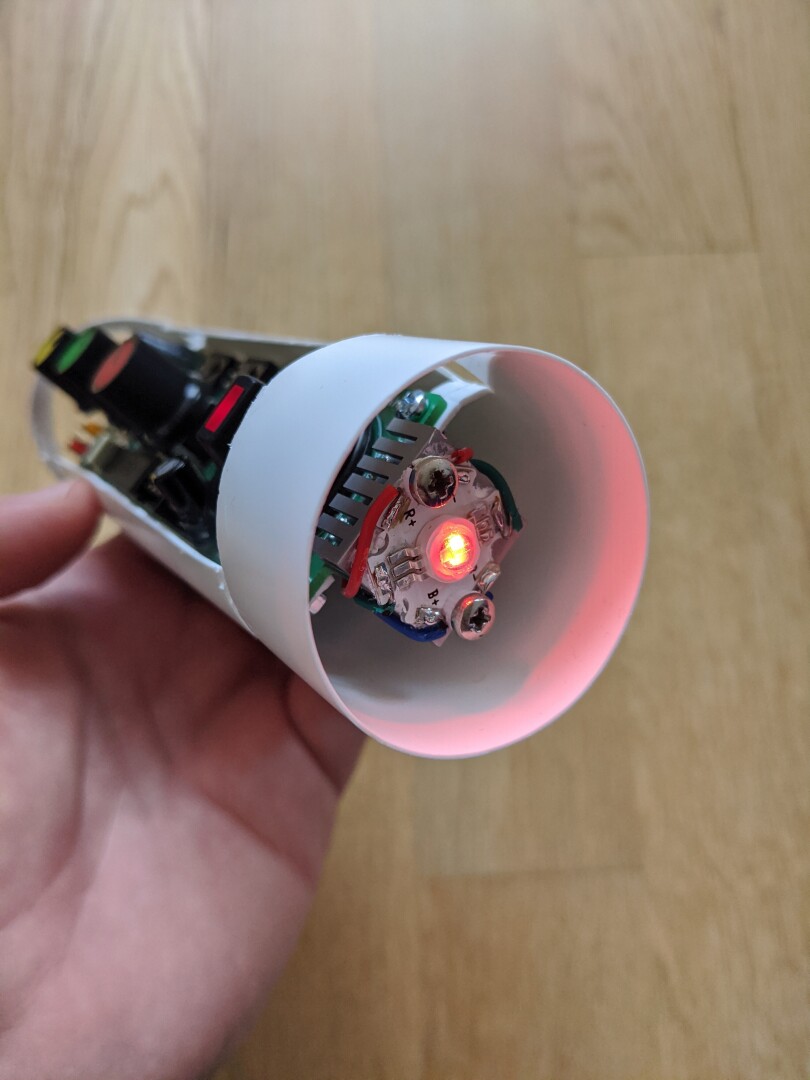
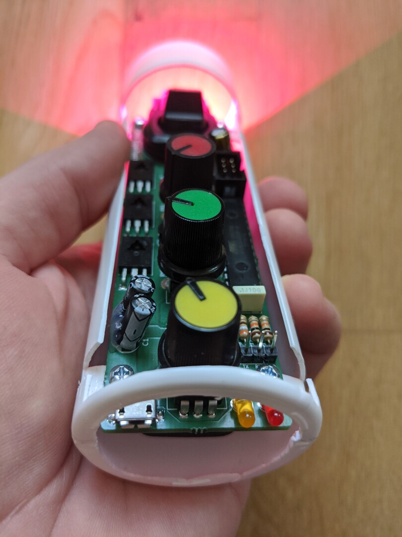
Highly unprofessional housing (click to enlarge)
The outer diameter of the tube is 45mm, and its length is cut to 140mm. There are mounting “ears” (flaps?) with holes in them for the four screws to fasten the board in place. The bottom cutout provides convenient access to the charging connector and indicator LEDs. Plenty of natural airflow for the heatsink, which is not too easy to touch by accident.
Conclusion
This little gadget has become a runaway success, front and center to many hours of fun, games and bedtime reading. It works exactly as it should. Luminance can be set anywhere between a faint glow (or actually, complete darkness) and blinding bright. The colors are strong and beautiful. Because the three components of the power LED are close but physically separate, obstacles will cast magical shadows with rainbows at their edges!
The only thing I added a posteriori was some “leaky bucket” rate limiting of output power to ensure that it won’t be carelessly left operating at a very high level, with the heatsink getting dangerously hot. If I were to do this again, I would just pick a bigger heatsink.
This time, I won’t bore you with details of hardware costs (bound to become irrelevant) and bill of materials lists. If you are so inclined, feel free to check out the full hardware design in KiCAD, published as part of the source code repo that is now published online with everything licensed under the terms of the very permissive MIT license.